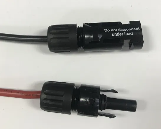
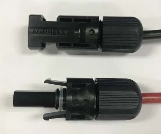
A 1MW power station has more than 3,500 sets of connectors on the DC side, and more than 100 connection points on the AC side. These connection points undertake the power transmission function in the power station, but they are prone to failure; according to incomplete statistics, the power station consists of 59% The problem comes from the connection problem. Good construction and good connector quality are the guarantee of a reliable, safe and efficient power station.
1.1 DC Side Connection
Introduce the crimping methods of two common types of inverter DC terminals (connectors), one is the MC4 terminal produced by Staubli (Multi-Contact); the other is the Amphenol H4 terminal produced by Amphenol.
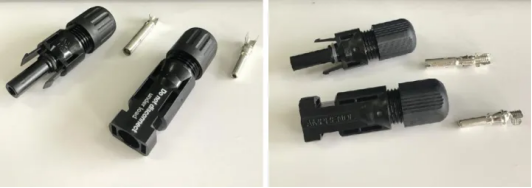
Staubli MC4 Amphenol H4
Precautions:
a. Use the connectors produced by the original factory or supplied by the inverter manufacturer; the inverter manufacturer’s inverter accessories box has enough spare connectors. If there is any loss or man-made damage, be sure to purchase the original connector device.
b. Connectors from different manufacturers are prohibited from inter-plugging. Inter-plugging connectors will lead to an increase in contact resistance, thereby reducing power generation efficiency, and will also accelerate the aging of plastics due to temperature rise, and the power station has a risk of fire. Inter-plugging connectors will also cause insulation The resistance is lower than the standard requirement, resulting in increased leakage current, reduced creepage distance, and thus the risk of electric shock.
1.2 Parameters Of The DC Solar Cable Connector
| Staubli MC4 | Amphenol H4 | |
| Rated Current | 30A (4mm , 10AWG) -IEC 90℃ 39A (4mm , 10AWG)-IEC 85℃ | 40A (4.0mm , 12AWG) |
| Rated Voltage | 1000V DC (IEC) | 1000V DC (IEC) |
| Test Voltage | 6kv (50Hz, 1min) | 6kV for 1min, 10kV impulse (1.2/50us) |
| Contact Resistance | 0.35mΩ | 0.35mΩ |
| Contact Resistance Stablity | Yes | Yes |
| Protection Level | IP68 | IP68 |
Ammonia Resistance Testing | Yes | Yes |
| Salt spray Testing | Yes | Yes |
| Recycled Materials | No | No |
1.3 Solar Connector Crimping Tool
| Tools | PIC | MC4 Crimping Steps | Amphenol Crimping Steps | |
| 01 | Automatic Wire Stripping | 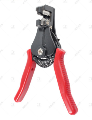 |  Use a wire stripper to peel off the outer skin of the cable, and peel off the metal part by about 6 to 7.5 mm. Use a wire stripper to peel off the outer skin of the cable, and peel off the metal part by about 6 to 7.5 mm. |  Use a wire stripper to peel off the outer skin of the cable, and peel off the metal part by about 6 to 7.5 mm. Use a wire stripper to peel off the outer skin of the cable, and peel off the metal part by about 6 to 7.5 mm. |
| 02 | Crimping Terminal Crimper | 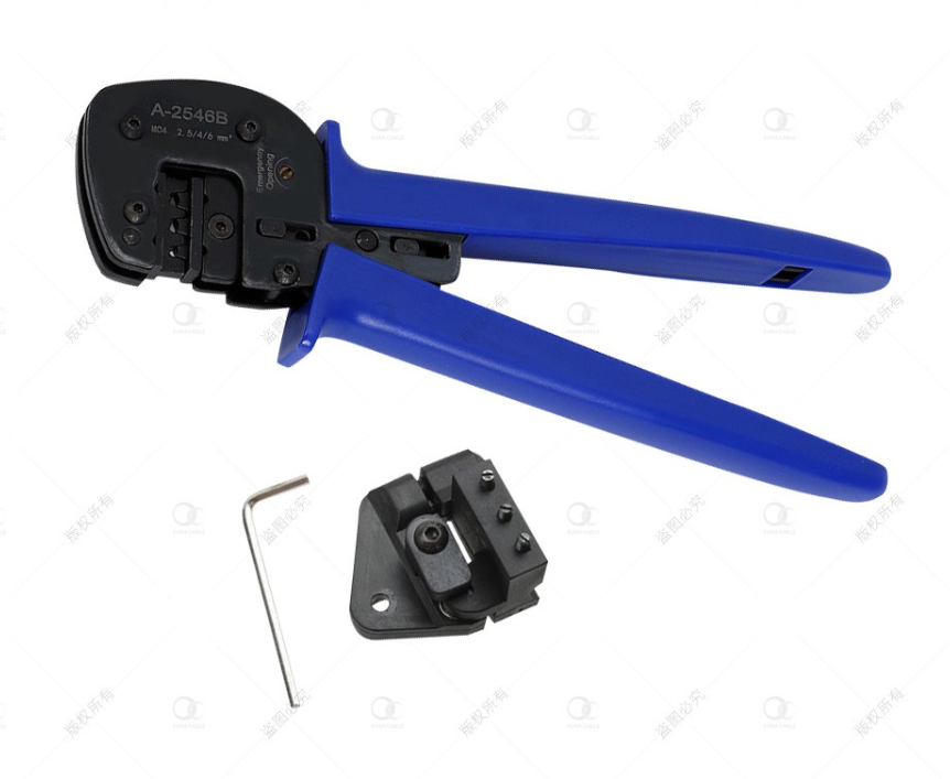 |  Use crimping pliers to crimp the cables. Use crimping pliers to crimp the cables. |
The method is the same as the MC4 terminal, but note that there is a limit buckle on the positive electrode of Amphenol, which cannot be crimped. |
| 03 | PV Spanner Wrench | 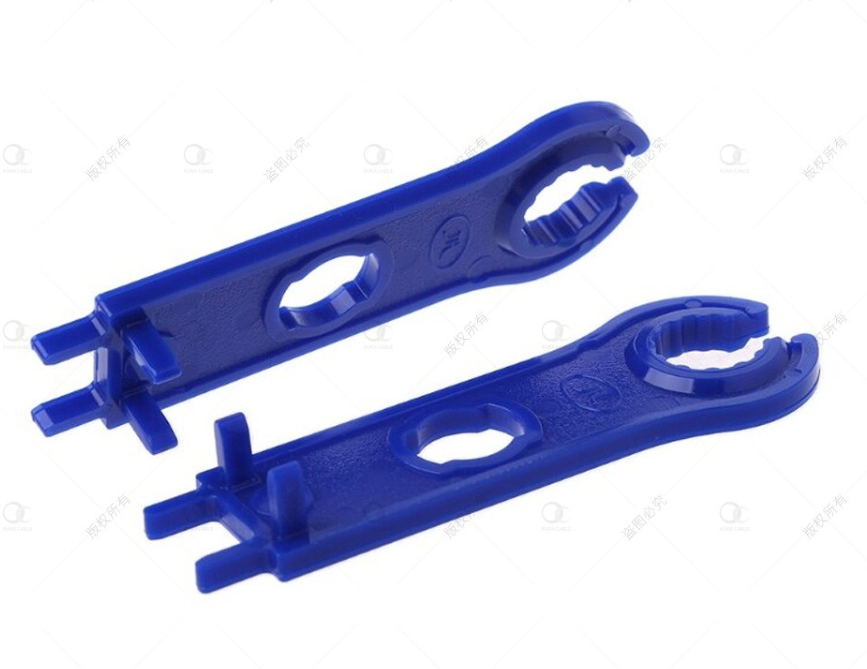 |
Tighten MC4 with MC4 Spanner Wrench. |
Tighten MC4 with MC4 Spanner Wrench. |
Precautions:
a. The PV+ and PV- cables are distinguished by color (such as red and black wires), otherwise it is easy to reverse the connector and cause the string to fail to work. When plugging in, to ensure that there is no reverse connection, it is necessary to detect whether the PV+ to PV- voltage is a positive voltage, and the lines of the same color need to be marked to distinguish.
b. The metal sheet and the terminal cannot be reversed, the positive hole is connected to the large-diameter metal sheet, and the negative electrode hole is connected to the small-diameter metal sheet.
c. When you hear a "click" sound when inserting the cable, it means that the cable has been plugged in. At this time, you can tighten it. When tightening the nut of the connector, the nut does not need to be screwed to the bottom, otherwise it will damage the connector itself or waterproof.
1.4 Common Faults Of DC Solar Connectors

The nuts are not tightened to the same degree. The positive and negative electrodes are not inserted properly.

The crimped copper wire fracture contact plate is inserted too deeply, and the connector is suspended.
1.5 Connection Check And Operation Maintenance
Visual Inspection
Visual inspection of the connector, such as whether the connector shell is damaged or deformed; whether there is stress on the cable; whether the connector is placed in the air. whether the connector is mated and the nut is tightened in place; change; whether there is an odor, etc.
Pull Test
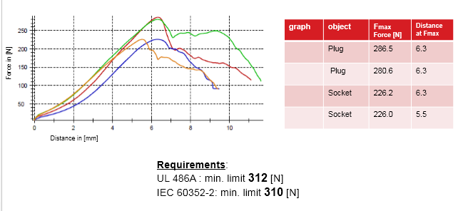
A well-crimped connector can withstand a pulling force of at least 310N. Try to pull the cable (not too much force) to see if the cable will fall off.
Infrared Thermal Imager
Terminals with poor crimping and connection have a high temperature, and can be detected by infrared thermal imaging during a long time and when power generation is good.
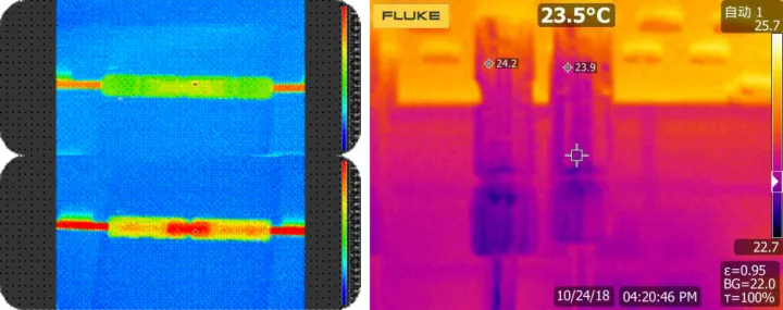
Good Crimp VS Bad Crimp


