Whether you have a PWM controller or an MPPT regulator, the process of connecting it to the battery and panel is the same. Typically there are three wiring sections on a charge controller: one for the panel, one for the battery, and one for the DC load.
1. Take a simple multi-strand copper core wire.
2. Match the charge controller "-" with the battery "-" with the black battery wire.
3. Pair the charge controller "+" with the battery "+" with the red battery wire
4. Screw the wires into the charge controller.
Turn on the charge controller: it should be able to measure the charge of the battery.
There should be a wiring diagram in the instruction manual of the charge controller, and you can refer to it if you have any questions.
PV modules

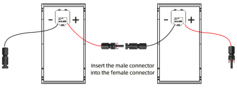
With the charge controller connected to the battery, it is now safe to attach it to the panel. From the panel's junction box there are two solar cables, positive and negative. In some cases it's just two wires connected directly to the controller. More commonly, there are so-called MC4 connectors on each end, a "male" connector for the positive cable and a "female" connector for the negative cable.
1. Connect the MC4 connector to the other end of a complementary pair of connectors. Skip this step if you have two wires coming directly from the junction box.
2. Plug these wires into the regulator: positive into "Positive" and negative into "Negative".
3. After connecting the panels to the controller, it should be able to recognize them. Check the status of the array on the charge controller screen.
4. The photovoltaic module starts to generate electricity as soon as it faces the sun.
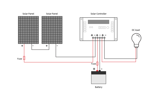
Here is the diagram that gives an idea of how to wire these parts of the solar panel system together. We have a 12V solar cell, a 96A MPPT controller and two 330W solar panels.

If you have several solar panels, as shown, the positive cable from one panel is usually connected to the negative terminal of the adjacent panel. Then, the negative cable from the first panel and the positive cable from the last panel go to the charge controller. The panels are connected in series, which means their voltages are combined, but the amperage remains the same.
In this small panel system, each panel has about 38V. Since the panels are connected in series, their combined voltage is 38V * 2 = 76V. Their amperage is
330W ÷ 38V = 8.7A
The battery voltage is 12V. The PWM controller will just step down the voltage of the panel to the level of the battery. So for the entire array at 660W, you only need to use 8.7A * 12V = 104W. However, since we have an MPPT charge controller, it allows the panel to maintain its power and speeds up the charging process of the battery. This battery can theoretically receive 660W ÷ 12V = 55A of current.


