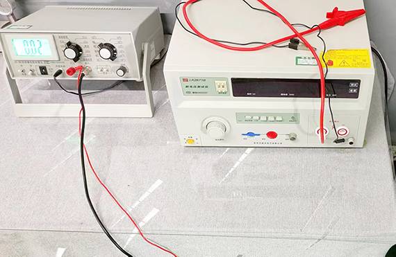
The PV cable conductor resistance test is a test method used to measure the resistance of conductors in solar cables. Solar cables typically include copper or aluminium conductors, which are used to transmit the electrical energy generated in a solar photovoltaic system. The resistance of the conductors is an important performance parameter as it directly affects the efficiency of the electrical energy transmission and the performance of the system.
The conductor resistance cable test is carried out on the whole cable or on a sample of cable of at least 1m in length and is measured in accordance with BS EN 60228. The test determines the DC resistance of Class 1, Class 2 and Class 5 Class 6 conductors for plain copper, metal-coated copper, aluminium and aluminium alloys, round or shaped. The standard specifies a nominal cross-sectional area ranging from 0.5mm 2 to 2500mm 2 and the results are expressed in Ohms/km.
Use a conductivity tester or resistance tester, these instruments are capable of measuring the resistance of cable conductors.

Connect the tester's probes to the ends of the cable to ensure a good cable connection. Then, apply a small current (usually at the microamp level) through the conductor and measure the voltage drop across the conductor. According to Ohm's Law, resistance can be calculated from the voltage drop and current.
Based on the measurement results, the resistance of the cable conductors is evaluated for compliance with design and performance requirements. Low resistance indicates efficient power transfer, while high resistance may result in energy loss and degradation of system performance.


